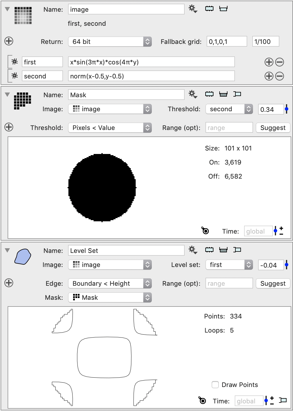
Level Set of Image
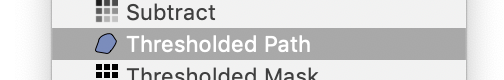
Create this object by selecting the “Thresholded Path” from the gear menu for an Image object.
This action has several names, depending on the field. This is often called a contour line, level set and not just thresholding.
The method is that for every cell in the image the method checks if a pixel values is above and another below. That means that in that cell the contour line will cut through it. The collection of all of these segements is then tied together to form one or more segments. Some of them are closed but those that end on the boundary are open.
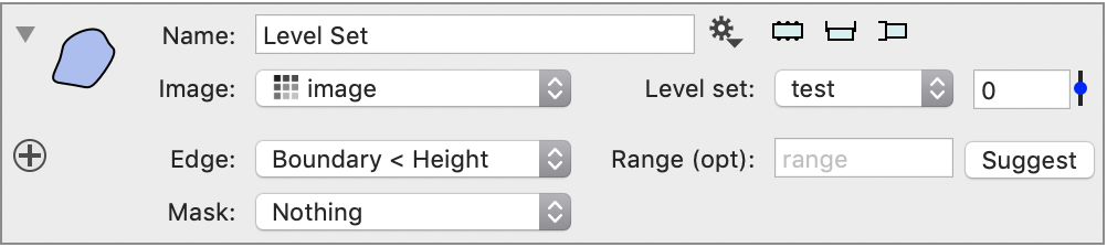
The options are
- You can select the field you want to take the contour of.
- The threshold value can be specified using a constant value or using local variables if you want it to depend on a value that is computed somewhere else
- You can pick what happens at the boundary. The default is to just end the segment at the boundary, but you can also choose to go along the boundary where the value is below or above the threshold.
- You can optionally select a Mask variable to restrict in space where the contour is computed.
- You can set a range that will be used for the slider next to the current contour value. This makes it easy to vary the contour value, but you can also use the side panel for that. The Suggest button will use the current time value of the channel to fill in the range.
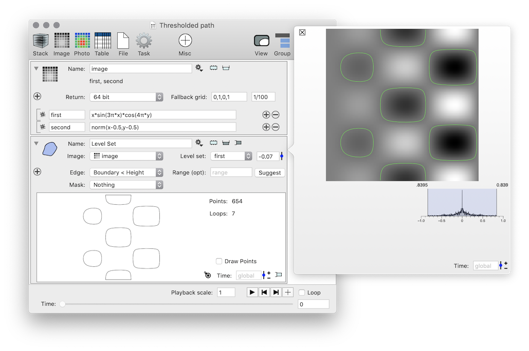
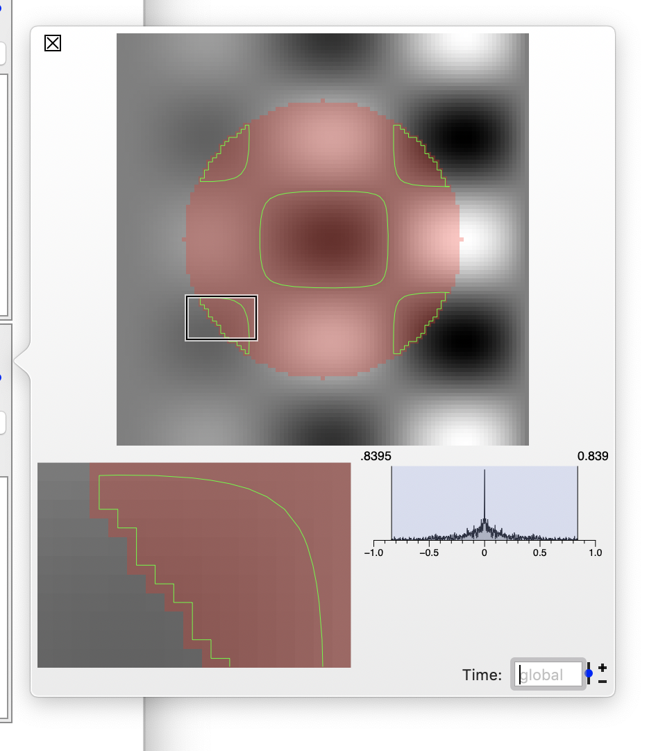
Side Panel
The side panel allows you to quickly see what effects the threshold has. You can also zoom in on a detail by selecting a cropping rectangle (see this for a description of how to vary that interactively).
Since the text is likely too small to read the expression used for the image is
x*sin(3π*x)*cos(4π*y)
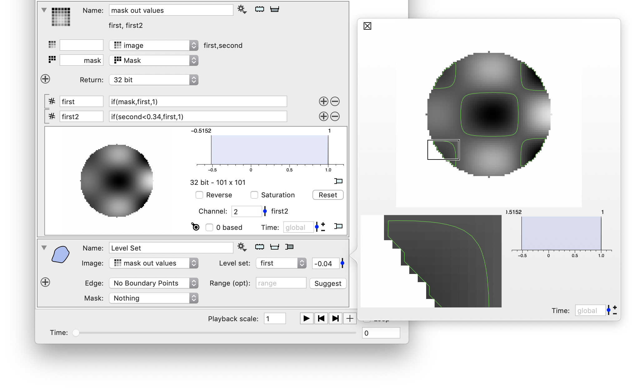
Specifying a Mask
If you specify a mask the contour finder will be restricted to cells where all four corners of the cell are included in the mask. For example, in the above example the second channel contains the distance from the center.
The thresholded mask option, which is very similiar to the thresholded path gives you a mask of 0/1 values. If you then selecct that mask you can see that the contour is restricted.
The side panel will overlay the mask as a semi-transparent layer so it is easier to see. Note that the boundary edge is included in this example and the edge follows the mask boundary.
Process before Contouring
Another way to get the effect of a mask is to use the Image Computation action to map the fields. You can get this effect by using both the mask and also an expression that computes the mask (first2). To add the mask to the list of input variables click on the + button to the left of the “Return” field. This variable needs to have a name, the name for the image can be left out. If you leave it out the channels are called first and second and can be used in the expression. If you specify a name, for example foo, the channel names are foo.first and foo.second